GIS Exercise 1 - Part 1 task
first What is a Gauss-Krüger-System (GK) system?
The Gauss-Krüger coordinate system is a Cartesian coordinate system. It allows sufficiently small areas of the globe with metric coordinates, ie Easting and Northing to locate, compliant.
The grid of geographical coordinates is divided into 3 ° wide meridian strips. Each meridian strip goes from the North to the South Pole so-called parallel to its central meridian. The central meridians Meridian adjacent strips are therefore 3 ° apart.
Each meridian strip is given a code number, which is derived from the number of degrees of the central meridian (0 °, 3 °, 6 ,...)
second Which units are to GK coordinates?
There are legal values and high values in the SI unit Meters are given.
third What is an ellipsoid, which is used in the GK system?
An ellipsoid is a higher-dimensional equivalent of an ellipse.
level sections of this body shall all ellipses or circles dar. The surface of the ellipsoid can be described mathematically, so that positions are specified by coordinates on the surface.
An ellipsoid that approximates most closely the surface of the whole earth is called a global geodetic datum. When GK is
system (also called Bessel 1841), the Bessel ellipsoid used. It was derived in 1841 by Friedrich Wilhelm Bessel. The data was large-scale Measurements.
4th Which Project is based on the Gauss-Krüger system? (Briefly explain)
The Gauss-Krüger system is based on a Transverse Mercator projection. Here, a cylinder is placed around the earth, it touches the equator. Transferring now all points on the cylinder and rolls them, one obtains a two-dimensional map of the earth. Since this is not angle-preserving, the map is distorted in North-South direction.
5th What is the difference between geographic and projected Cartesian coordinates?
Geographic coordinates are the coordinates of the position of a point on the Earth's surface. This is based on a graticule consisting of longitude and latitude. The starting points are the equator and the prime meridian.
Geographic coordinates are ALSO in the angular setting of points on the surface, starting from the equator, and uses the zero meridian.
Cartesian coordinates describing the position of a point in space. Reference system is a two-or three-axis orthogonal system, consisting of the axes x, y, (z).
6th Why are used in the GK system called meridian strip?
Man you tried distortions in the Mercator projection, north and south of the equator caused by so-called reduce meridian strip. The earth is here divided in 3 ° wide strips (strips Meridian). Each of these strips is a separate rectangular coordinate system dar. The x-axis coordinate system is related to the respective central meridian, which refers to the y-axis is always on the equator.
7th As you can see the number of the meridian strip used in a coordinate?
The code is the first in the coordinate, each principal meridian has its own identification number that is calculated by dividing by the number of degrees of the main meridian by 3 divided
Monday, May 3, 2010
Friday, April 30, 2010
Two Stroke Generator Oil
IRRGANG - ein neuer Stummfilm
Irrgang from APEIRON FILMS on Vimeo .
Eine melancholische Parabel über die Clownerie des Verliebens. Manche Menschen sind wie aus Stein, wenn sich ihnen die Verliebten mit ihren Gesten und Geschenken nähern. Wie gehen diese damit um? Lernen sie aus ihren Versuchen?
Dieser Stummfilm von Diana und Dave basiert auf einem Gedicht von Goethe (Liebhaber in allen Gestalten). Wie little is yet since the time of the poet in relation to interpersonal change is amazing.
We Irrgang KinoKabaret produced at Dresden in 48 hours without a budget. Cinema Gieno showed it 2 times then the Dresden Film Festival. 
Irrgang from APEIRON FILMS on Vimeo .
Eine melancholische Parabel über die Clownerie des Verliebens. Manche Menschen sind wie aus Stein, wenn sich ihnen die Verliebten mit ihren Gesten und Geschenken nähern. Wie gehen diese damit um? Lernen sie aus ihren Versuchen?
Dieser Stummfilm von Diana und Dave basiert auf einem Gedicht von Goethe (Liebhaber in allen Gestalten). Wie little is yet since the time of the poet in relation to interpersonal change is amazing.
We Irrgang KinoKabaret produced at Dresden in 48 hours without a budget. Cinema Gieno showed it 2 times then the Dresden Film Festival.
Tuesday, February 9, 2010
Street Value Valium 5mg
Exercise 6 - positions with AutoCAD
object of this exercise was using the program AutoCAD a design plan in 2D draw and dimension the proposed building.
First step: First, a digital basis
be created. This requires that you import the digital basis for zoning as a JPG file.
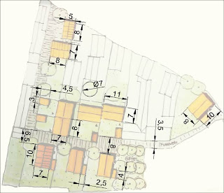
Second step: After
need to create a precisely dimensioned construction. The building dimensions are specified on the attached plan.
With the help of the tools "line" and "square" one can trace the lines given. To get the correct angle, you can view at the "BKS_Koordinatensystem" select and adapt the plan element to be processed. To colorize
the elements of the plan, there is the tool shading. One chooses a color and an object that is to be dyed.
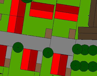
Next Step three parts of the plan must be provided with dimensions. For this you choose the tool aimed at dimensioning of view. It is where the corners of the objects to be dimensioned, and draws a line where the label is.

Fourth step:
be layouted The last step is the plan yet. These start in the layer "layout" You can pull up box and paste there the plan. Using the Tools "square" you can create a legend. The text can be created using the tool "Individual Line" and title, legend, etc. insert processor. The text size is to click Edit by the text
pavers Plan:
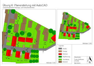
Link Plan to PDF:
http://www.fileuploadx.de/410384 
object of this exercise was using the program AutoCAD a design plan in 2D draw and dimension the proposed building.
First step: First, a digital basis
be created. This requires that you import the digital basis for zoning as a JPG file.

Second step: After
need to create a precisely dimensioned construction. The building dimensions are specified on the attached plan.
With the help of the tools "line" and "square" one can trace the lines given. To get the correct angle, you can view at the "BKS_Koordinatensystem" select and adapt the plan element to be processed. To colorize
the elements of the plan, there is the tool shading. One chooses a color and an object that is to be dyed.

Next Step three parts of the plan must be provided with dimensions. For this you choose the tool aimed at dimensioning of view. It is where the corners of the objects to be dimensioned, and draws a line where the label is.

Fourth step:
be layouted The last step is the plan yet. These start in the layer "layout" You can pull up box and paste there the plan. Using the Tools "square" you can create a legend. The text can be created using the tool "Individual Line" and title, legend, etc. insert processor. The text size is to click Edit by the text
pavers Plan:

Link Plan to PDF:
http://www.fileuploadx.de/410384
Monday, January 18, 2010
Where To Put Powder In A Washing Mashine
5.Übung - 3D city model
Building on Exercise 4 "facade correction" should now created in this exercise, a 3D city model of the Ludwig center in Saarbrücken with the program "Sketch Up" be.
First step:
The predetermined schedule basis, the program opened Sketch Up
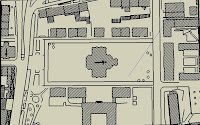
Second step:
The contours of the building will now be traced using the tool "line". This results in a closed area. That area can use the tool to "push / pull" pull up and adjust to the height of the building. The initial height of the building is 9 feet, the ground level of the church 12 meters.
Third step:
Now the roofs are constructed. It first determines the center line on the area where the roof is provided. This line can be pulled up with the tool "Move / Copy" to the desired height, in our case, 5 meters in the houses and 8 meters at the church. Even smaller roof elements (such as gable) can be modeled in this way.
The roof surfaces can use the "paint bucket" in which you various fillings, such as bricks, floor coverings etc can choose to be dyed.
Fourth step: To construct
dormers, first a vertical rectangular surface is created on the roof. This area can be extracted with the Push / Pull "tool to the rear and a dormer to be modeled. The peak is created in the same way.
Step Five:
Now the fronts are set to the building. The equalized in exercise 4 façades (How Equalization see Exercise 4) serve as a texture base. To put the facades of the buildings, first the Photoshop file (in power of two format) are imported into the program: File - Importieren – Bild auswählen – als Textur verwenden.
Die Textur wird an zwei Eckpunkten des Gebäudes montiert und wird nun angepasst. Man wählt per Rechtsklick die Funktion „Textur - Position“ aus. An den gelben Reißzwecken kann man die Textur verändern.
Sechster Schritt:
Als letztes werden Die Bodenflächen mit Hilfe des „Farbeimers“ eingefärbt und Elemente wie Personen und Bäume eingefügt.
Elemente dieser Art finden man bei: Fenster – Komponenten – Komponente auswählen – platzieren.
Gebäude am Ludwigsplatz: Original und 3D

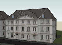
3D Ansicht des Ludwigsplatzes

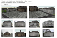
Weitere Aufgabenteile der Übung waren das erstellen eines Gesamtplanes mit Corel Draw und eine CD mit allein Dateien.
Plan mit Corel Draw

Building on Exercise 4 "facade correction" should now created in this exercise, a 3D city model of the Ludwig center in Saarbrücken with the program "Sketch Up" be.
First step:
The predetermined schedule basis, the program opened Sketch Up

Second step:
The contours of the building will now be traced using the tool "line". This results in a closed area. That area can use the tool to "push / pull" pull up and adjust to the height of the building. The initial height of the building is 9 feet, the ground level of the church 12 meters.
Third step:
Now the roofs are constructed. It first determines the center line on the area where the roof is provided. This line can be pulled up with the tool "Move / Copy" to the desired height, in our case, 5 meters in the houses and 8 meters at the church. Even smaller roof elements (such as gable) can be modeled in this way.
The roof surfaces can use the "paint bucket" in which you various fillings, such as bricks, floor coverings etc can choose to be dyed.
Fourth step: To construct
dormers, first a vertical rectangular surface is created on the roof. This area can be extracted with the Push / Pull "tool to the rear and a dormer to be modeled. The peak is created in the same way.
Step Five:
Now the fronts are set to the building. The equalized in exercise 4 façades (How Equalization see Exercise 4) serve as a texture base. To put the facades of the buildings, first the Photoshop file (in power of two format) are imported into the program: File - Importieren – Bild auswählen – als Textur verwenden.
Die Textur wird an zwei Eckpunkten des Gebäudes montiert und wird nun angepasst. Man wählt per Rechtsklick die Funktion „Textur - Position“ aus. An den gelben Reißzwecken kann man die Textur verändern.
Sechster Schritt:
Als letztes werden Die Bodenflächen mit Hilfe des „Farbeimers“ eingefärbt und Elemente wie Personen und Bäume eingefügt.
Elemente dieser Art finden man bei: Fenster – Komponenten – Komponente auswählen – platzieren.
Gebäude am Ludwigsplatz: Original und 3D


3D Ansicht des Ludwigsplatzes

Weitere Aufgabenteile der Übung waren das erstellen eines Gesamtplanes mit Corel Draw und eine CD mit allein Dateien.
Plan mit Corel Draw

Subscribe to:
Posts (Atom)